

A damaged bearing rarely tells the whole story. Turbine bearing failure analysis matters because it connects physical damage with operating conditions and lubrication evidence to identify likely causes and prevent repeat failures. After a failure, preserve the components and collect at least 72 hours of pre-event operating data before handling or cleaning can remove useful clues.
It is understandable to focus first on the failed component, but the cause may lie in a chain of damage, operating conditions and lubrication issues. A structured investigation can distinguish these factors and give maintenance teams a sounder basis for decisions.
This guide explains how microscopy and chemical testing can reveal evidence that visual inspection may miss, and how failure databases help compare damage patterns, materials and operating environments. It also covers common bearing failure causes and how oil analysis can help interpret lubrication-related evidence.
Key Takeaways
- Use vibration trends alongside physical inspection to build a clearer picture of bearing condition; ISO 20816-1 provides general guidelines for measuring and evaluating machine vibration.
- Microscopy and chemical testing can uncover material, surface or lubrication clues that a visual inspection alone may not reveal.
- Apply ISO 15243’s framework to classify rolling bearing damage by its characteristics, appearance and possible causes.
- Compare failure evidence across bearing designs, materials, heat treatments, operating environments and lubrication conditions to identify patterns that may guide future decisions.
Why Is Wind Turbine Bearing Failure Analysis Important?
Analysis connects bearing damage with operating conditions, helping teams make informed maintenance decisions. Preserving evidence before cleaning or dismantling protects clues that may help distinguish causes.
Preserving Failure Evidence
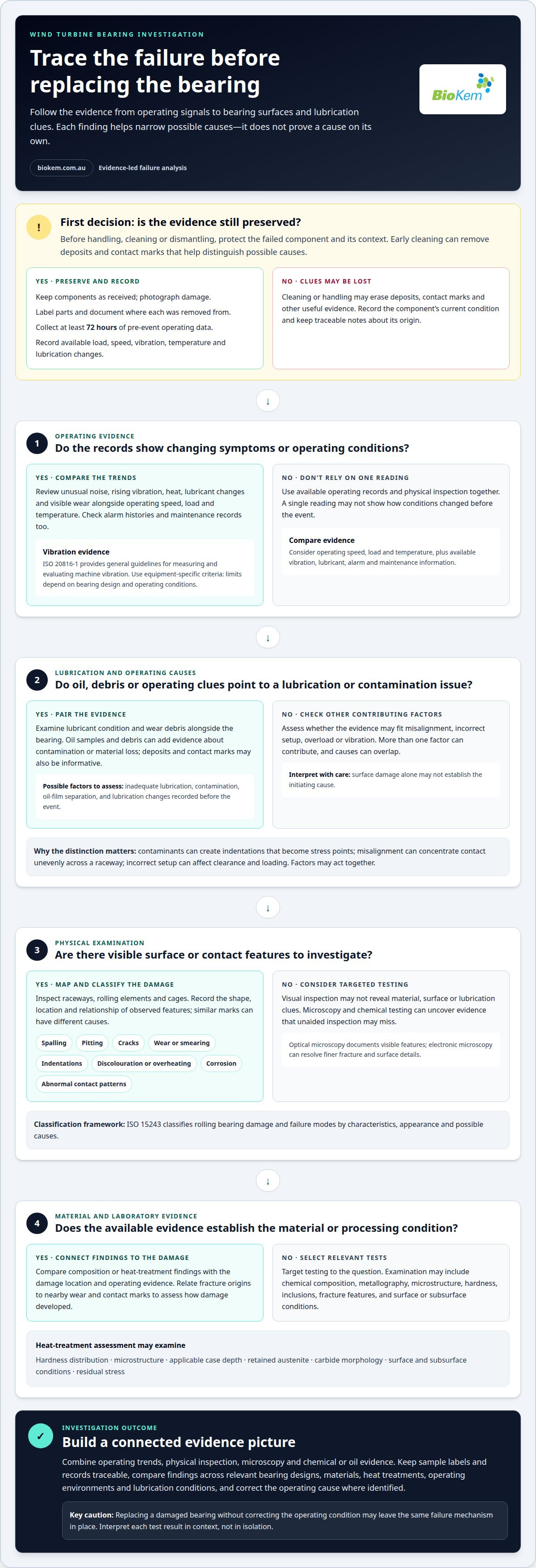
Preserving evidence means recording operating conditions and protecting the failed bearing before examination. Keep components as received, photograph damage, label parts and document where they were removed from. Gather available operating records from before the event, including load, speed, vibration, temperature and lubrication changes. Early cleaning can erase deposits and contact marks, making later comparisons and root-cause findings less reliable.
Common Causes of Bearing Failure
Failure causes include lubrication problems, contamination, misalignment, incorrect setup, overload and vibration. Their effects can overlap, so identifying a damaged surface alone may not establish the initiating cause. The International Organization for Standardization (ISO) says ISO 20816-1 provides general guidelines for measuring and evaluating machine vibration.
Repair may require correcting the operating cause and repairing or replacing the bearing. Costs depend on bearing design, the extent of damage, access and associated work. In Australia, inspection and repair decisions should also account for site safety controls and equipment requirements.
Damage Symptoms and Operating Data
Symptoms can include unusual noise, rising vibration, heat, lubricant changes and visible wear. Compare trends with operating speed, load and temperature rather than relying on a single reading. Review alarm histories and maintenance records alongside the physical evidence. Clearance, vibration and temperature limits depend on bearing design and operating conditions, so use equipment-specific criteria rather than a generic figure.
Diagnostic Analysis Methods
Engineers combine vibration patterns, lubricant condition and temperature trends to assess damage. ISO 20816-1 guides vibration measurement and evaluation; oil samples and wear debris can add evidence about contamination or material loss. Wear debris analysis can support this investigation. Together, these findings help separate lubrication-related wear from mechanical or operational causes and guide the next maintenance decision.
Advanced microscopy and chemical analysis
Laboratory examination can reveal damage mechanisms that unaided inspection cannot distinguish. It connects surface features and material properties with the bearing’s failure pattern.
Microscopy of Failed Bearings
Microscopy magnifies raceways, rolling elements and cages to examine surface and subsurface damage. Investigators look for spalling, pitting, cracks, wear, smearing, indentations, discolouration, overheating, corrosion and abnormal contact patterns. Optical microscopy documents visible features, while electronic microscopy can resolve finer fracture and surface details. This distinction matters because similar marks can have different causes; their shape, location and relationship help narrow the possibilities.
Chemical Analysis and Inspection Process
Chemical and spectrographic analysis can assess material composition when visual evidence does not establish the root cause. A practical examination progresses from documentation to close inspection and then targeted testing: record part identity and condition, map damage locations, photograph surfaces and select samples from relevant areas. Testing may cover chemical composition, metallography, microstructure, hardness, inclusions, fracture features, and surface or subsurface conditions. Each result adds evidence, but should not be interpreted in isolation.
Heat-treatment assessment can examine hardness distribution, microstructure, applicable case depth, retained austenite, carbide morphology, surface and subsurface conditions, and residual stress. These findings may help distinguish material or processing factors from operational damage. Comparing a fracture origin with nearby wear and contact marks can also show how the damage developed, rather than merely describe its final appearance.
Clear sample labelling and traceable records keep test results connected to the correct component and location. For lubrication evidence, pair bearing findings with relevant oil and debris results. If you need to discuss how oil evidence fits an investigation, contact the technical team.
In wind turbine investigations, examinations can assess raceways, rolling elements and cages for spalling, pitting, cracking, wear, smearing, indentations, discolouration, overheating, corrosion and abnormal contact patterns.
What are the common causes of turbine bearing failure?
Common causes include inadequate lubrication, contamination, incorrect bearing setup, misalignment and unstable operating conditions. These factors can act together: contamination may damage a surface, while poor lubrication accelerates wear. The International Organization for Standardization (ISO) provides ISO 15243 as a standardised framework for classifying rolling bearing damage and failure modes by their characteristics, appearance and possible causes.
Lubrication problems arise when the oil film cannot adequately separate contacting surfaces. Contaminants can create indentations that become stress points, while misalignment can concentrate contact unevenly across a raceway. Incorrect setup can also affect bearing clearance and loading. Identifying the initiating cause matters: replacing a damaged bearing without correcting the operating condition may leave the same failure mechanism in place.
A published case study of GE Frame 9001E gas turbines rated at 112 MW identified leading-edge lockup associated with inadequate bearing setup and vertical misalignment. This example shows why investigators should connect physical damage with installation and alignment evidence, rather than relying on appearance alone. A low-amplitude 0.5X subsynchronous vibration component appearing at higher speeds is also a recognised sign of lubricating-film instability.
Classifying the damage pattern helps organise the evidence. Surface distress, abnormal contact and vibration behaviour, for example, can point towards different mechanisms, but no single observation proves the root cause. Compare bearing condition with operating records, lubrication history, alignment information and vibration trends. Taken together, these clues can help distinguish a primary cause from secondary damage that developed later.
If lubrication evidence forms part of your investigation, discuss the relevant oil analysis options.
When visual examination cannot reliably establish the root cause of bearing failure, investigations may rely on specialist inspection partners such as International Testing Services Ltd to examine the evidence further using optical or electronic microscopy and chemical or spectrographic analysis.
BioKem Oil Services: Hot Oil Flushing
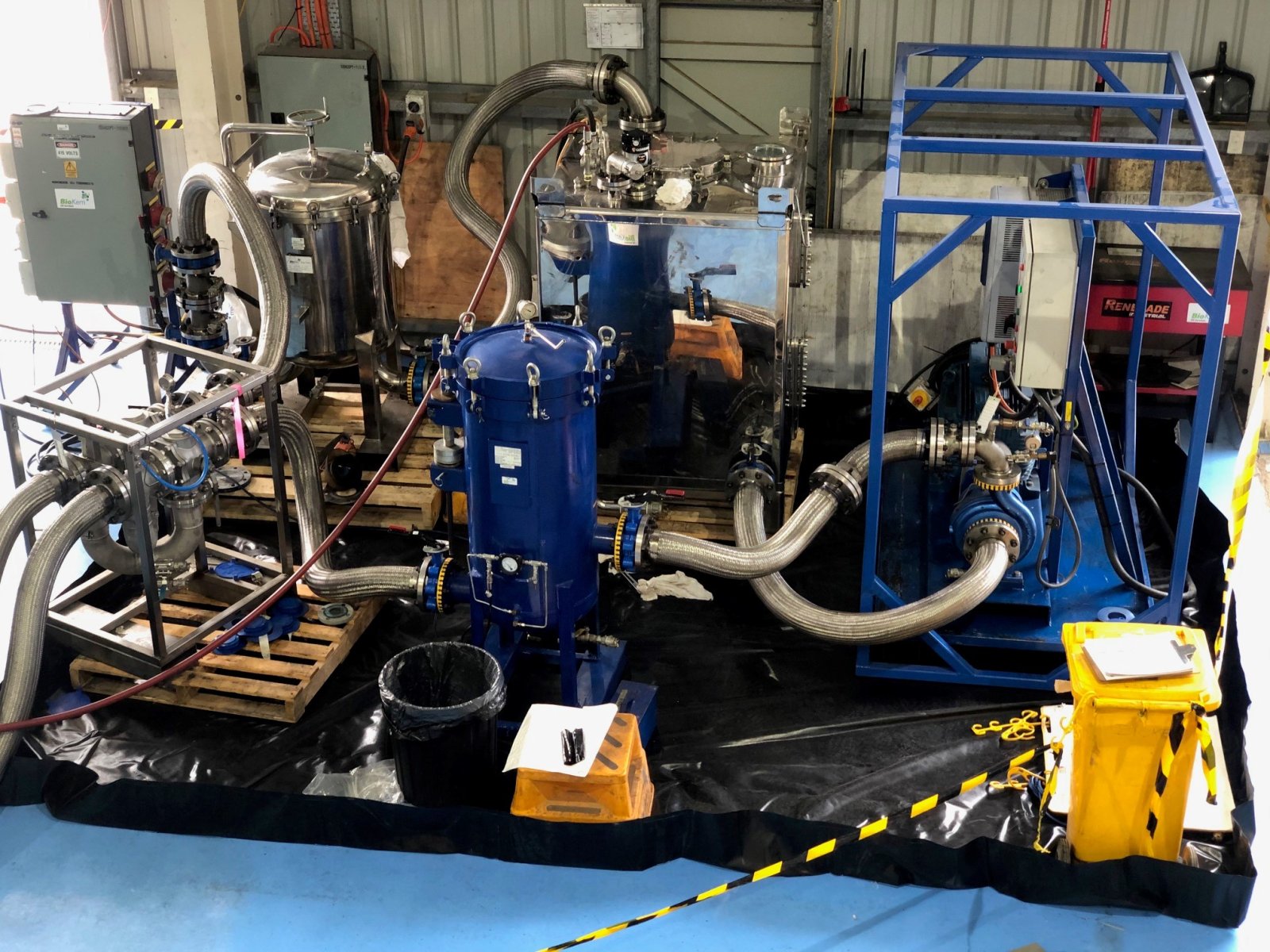
BioKem Oil Services provides Hot Oil Flushing for turbine lubrication systems where oil-circuit cleanliness is a maintenance concern. The service may be relevant after contamination is identified or when system cleaning forms part of planned maintenance. The appropriate response depends on the oil, deposits and equipment condition.
If analysis identifies other oil-condition issues, BioKem Oil Services also offers Oil Analysis, Varnish Mitigation and Vacuum Dehydration. These services address different maintenance needs, so investigation findings can guide the next step instead of treating every bearing failure as an oil problem. Maintaining clean, suitable lubricant supports equipment care, but does not replace identifying and correcting the underlying failure mechanism.
Contact BioKem Oil Services to discuss your turbine lubrication requirements.
Turn findings into a stronger maintenance plan
A bearing investigation is most useful when its findings inform decisions beyond the immediate repair. Use the identified failure mechanism to review inspection priorities, lubrication controls and the operating conditions that contributed to damage. This connects engineering evidence with practical asset-care planning, rather than treating each failure as an isolated event.
A disciplined turbine bearing failure analysis can also inform oil-condition management throughout the equipment lifecycle. BioKem Oil Services offers Hot Oil Flushing, Varnish Mitigation and Vacuum Dehydration for relevant oil-system needs. The right maintenance response depends on the evidence and the system’s condition.
Discuss your turbine lubrication requirements with BioKem Oil Services and take a considered next step towards reliable equipment care.
Frequently Asked Questions
What are the main turbine bearing failure modes and their physical signs?
Common failure modes include spalling, pitting, cracking, smearing, wear and corrosion, each with distinct surface evidence. Spalling appears as material flaking from a loaded surface; pitting forms small cavities, while smearing creates a dragged or streaked finish. Cracks may begin near a damaged area, and corrosion can leave etched or discoloured patches. Record each feature’s location and direction before interpreting it.
How can bearing failure root causes be distinguished from secondary damage?
To separate root causes from secondary damage, trace where and how the damage began, then compare the pattern with operating and maintenance records. A localised origin followed by spreading damage, for example, suggests a different sequence from widespread distress across multiple contact areas. Examine fracture surfaces and material condition alongside lubrication and operating evidence; the earliest damage feature can provide an important clue to the initiating mechanism.

Article by
James McAllister
James McAllister is an industry professional with BioKem Oil Services, specialising in lubrication reliability, oil filtration, contamination control and asset performance. Drawing on BioKem's extensive field experience across turbines, compressors, hydraulic systems and critical rotating equipment, James writes practical, insight-driven articles that help maintenance and reliability teams improve equipment performance, extend asset life and reduce operational risk.