

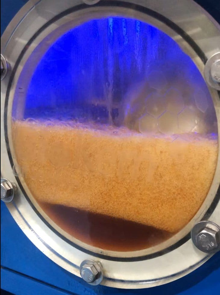
Passive lubricant circulation does not decontaminate critical machinery; it simply washes clean fluid over settled debris. True industrial lubrication system flushing demands deliberate, high-velocity fluid dynamics and targeted thermal cycling to dislodge stubborn varnish precursors, pipe scale, and residual maintenance debris from intricate pipework before initial plant start-up.
Plant engineers know the acute frustration of premature bearing failure or sticking servo valves shortly after an overhaul. When turnaround schedules tighten, managing the technical friction between laminar flow limitations, turbulent velocity calculations, and strict Australian environmental and safety standards leaves zero room for trial and error.
This guide provides the exact engineering blueprint to plan, specify, and execute a high-velocity flush that satisfies demanding OEM cleanliness criteria. You’ll master the Reynolds number thresholds required to guarantee turbulent mechanical scrubbing, learn how thermal manipulation frees surface varnish, and establish an audit-ready protocol that achieves target ISO 4406 fluid cleanliness codes before your critical rotating assets spin up.
Key Takeaways
- Effective lubrication system flushing relies on achieving fully turbulent fluid dynamics (Re > 4,000) to mechanically dislodge settled particulate, scale, and silt from internal piping walls.
- Protecting sensitive journal bearings and proportional valves demands rigorous physical isolation and bypass loops prior to initiating high-velocity circulation.
- Dynamic thermal cycling during hot oil flushing alters fluid viscosity and dissolves stubborn varnish precursors that standard drain-and-fill practices leave behind.
- Establishing repeatable, audit-ready verification protocols against ISO 4406:2021 cleanliness codes ensures rotating plant reliability before startup.
- Selecting an Australian industrial flushing partner requires auditing their skid pumping volumes, thermal heating capacities, and verified safety track records on critical sites.
Understanding Industrial Lubrication System Flushing: Objectives and Critical Triggers
Industrial lubrication system flushing is a specialized mechanical and thermal decontamination process, not routine oil circulation. Standard installed pumps cannot clear contaminated lines because they are sized strictly to supply steady lubricant volume at component tolerances. This baseline operation generates sluggish, laminar flow that glides smoothly over settled pipe wall debris without lifting it. Truly scouring an industrial circuit requires dedicated external pumping rigs that push fluids well past boundary-layer friction limits.
To observe how temporary circulation loops are configured on site, watch this setup in action:
Primary Contaminant Types in Industrial Lubrication Circuits
Industrial fluid loops accumulate distinct contaminant groups, each demanding specific physical or chemical mitigation strategies:
- Hard particulates: Construction swarf, silica, mill scale, and abrasive weld spatter that rapidly scar babbitt bearings and precision journal surfaces.
- Soft degradation products: Sub-micron oil oxidation products, sludges, and thermal varnish precursors. Capturing these polar molecules often requires coupling an offline varnish removal system directly into the flushing loop to strip deposits from valve spools before recommissioning.
- Moisture: Free, emulsified, and dissolved water that degrades additives and induces rust. Coupling an industrial vacuum dehydration oil purification system draws moisture down below oil saturation thresholds during circulation.
Critical Operating Milestones Requiring a Comprehensive System Flush
Certain plant milestones make rigorous lubrication system flushing mandatory. During capital commissioning or post-turnaround rebuilds, pipework contains atmospheric dust and fabrication slag. Maintenance engineers confirm proper fluid turbulence by calculating Reynolds numbers across each line size, ensuring fluid shear stresses break debris loose.
Catastrophic component failures also trigger urgent flushing requirements. When an internal bearing or gear set disintegrates, metallic wear fragments spread through downstream headers and coolers. Flushing is equally vital during lubricant conversions, purging depleted residue to prevent oil cross-contamination and additive dropout.
Step-by-Step Methodology: Executing a High-Velocity Lubrication System Flush
Executing an effective lubrication system flush requires a sequenced engineering protocol rather than improvised field work. Following established guidelines such as the ASTM flushing and cleaning standard (ASTM D6439), this three-phase framework clears circuits systematically without jeopardising delicate rotating assemblies. Many site teams coordinate these technical steps alongside specialized commissioning and shutdowns turnaround services to ensure smooth integration with broader plant schedules.
Phase 1: Pre-Flush System Isolation and Circuit Bypassing
Field teams begin by isolating all components sensitive to high-velocity debris impingement. Install solid spool pieces or flexible jumper hoses around journal bearings, thrust pads, servo valves, and precision flow meters. Never route unverified flush fluids across babbitt metal surfaces. Next, pump down the primary reservoir and clean its interior floor with lint-free wipes. External high-flow pumping skids and multi-bag filter vessels are then connected directly to the system’s battery limits.
Phase 2: Dynamic Thermal Cycling and Mechanical Agitation
Once bypassed, the flushing skid circulates a low-viscosity flush oil under elevated flow rates to induce turbulence. Operators cycle fluid temperatures dynamically between 40°C and 70°C. This constant heating and cooling causes pipework to expand and contract, breaking brittle mill scale away from internal surfaces. Technicians also apply targeted external mechanical agitation:
- Striking hard-to-reach pipe bends, elbows, and weld joints using non-marking dead-blow mallets.
- Mounting pneumatic vibrators on large-diameter headers to keep dislodged particulates suspended in the stream.
- Reversing flow direction through external manifold switching to scour pockets behind flanges.
Phase 3: Final Verification, Fluid Recommissioning, and Reintegration
System filtration progresses sequentially through 25-micron, 10-micron, and final 3-micron elements. Technicians verify particle dropoff using calibrated inline monitors and field patch test kits. Once the circuit meets specified fluid cleanliness metrics, drain the dedicated flush fluid completely. Inspect low-point dead legs for residual oil pockets, remove all bypass jumpers, reconnect OEM valves and bearings, and charge the circuit with fresh operational lubricant. If your plant is planning a major overhaul, you can consult BioKem’s engineering team to specify site-ready flushing infrastructure.
Evaluating Flushing Methodologies: High-Velocity Hot Oil vs. Conventional Approaches
Relying on a static drain-and-fill is one of the costliest shortcuts in industrial asset management. Simply draining a sump and refilling with fresh fluid leaves settled grit, wear metal, and degraded sludge resting quietly in horizontal pipe runs and dead legs. As soon as a turbine or compressor restarts, mechanical vibration sweeps these latent contaminants directly into sensitive components. True lubrication system flushing applies the fluid shear stresses required to lift and transport that debris completely out of the circuit.
Conventional Drain-and-Fill vs. High-Velocity Hot Oil Flushing
Standard oil changes rely on gravity, which cannot move silting settled in large-diameter headers. Dedicated hot oil flushing and filtering overcomes this physical limitation by driving fluid through pipework at two to three times normal operating velocity while heating it up to 70°C.
This dynamic approach delivers three distinct operational advantages:
- Elevated fluid velocity: Generates chaotic boundary-layer shear stress that scrubs adhering particulate and construction scale off interior walls.
- Reduced fluid viscosity: Lowering fluid viscosity via heating increases kinetic energy transfer, ensuring heavy metallic particles remain suspended rather than settling out.
- Lifecycle cost reduction: While a drain-and-fill appears cheaper upfront, it frequently leads to unplanned trips, servo valve sticking, and premature oil degradation that cost far more in lost production.
Integrating Chemical Cleaners and Varnish Removal Systems
When dealing with severe thermal degradation, maintenance planners often debate between adding chemical flushing agents or using mechanical extraction. Detergent and solvent-based chemical cleaners can dissolve soft insolubles quickly. However, chemical additives carry significant operational risks. If chemical residues remain trapped in pipe crevices, they degrade the water demulsibility, foam resistance, and oxidation stability of your fresh lubricant.
A more dependable strategy integrates dedicated varnish removal systems into the circulation circuit. Utilizing selective adsorption media and ion-exchange resins, these systems capture dissolved oxidation precursors and polar contaminants directly from the hot oil. This clears sticky lacquer from governor circuits without introducing harsh chemical contaminants that compromise your baseline fluid chemistry.
Technical Parameters: Calculating Reynolds Numbers and Cleanliness Targets
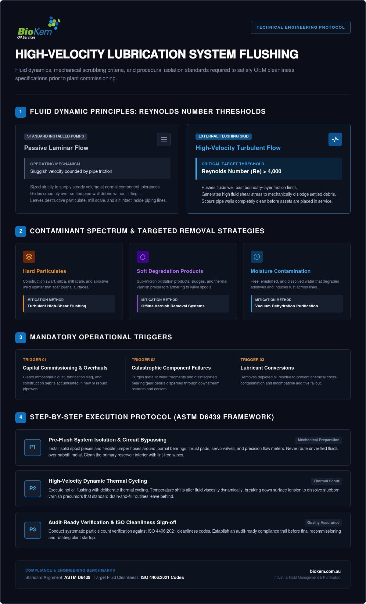
Achieving line clearance during lubrication system flushing requires precise mathematical verification rather than guesswork. Fluid mechanics govern particle detachment; if your flush doesn’t generate sufficient shear stress at the inner pipe wall, laminar boundary layers protect settled particulates from moving. Calculating exact velocity and Reynolds numbers is the only way to ensure internal scouring.
Achieving Turbulent Flow: Viscosity, Velocity, and Reynolds Number
The Reynolds number ($Re$) defines the boundary between laminar and turbulent flow within closed conduits:
$$Re = frac{V cdot D}{nu}$$
Here, $V$ represents fluid velocity in metres per second, $D$ is the pipe internal diameter in metres, and $nu$ is the fluid’s kinematic viscosity in square metres per second ($cSt times 10^{-6}$).
While theoretical turbulence begins at $Re > 4,000$, effective industrial line clearing demands sustained targets between 8,000 and 10,000. In rigid steel headers, targeting an $Re$ of 11,000 to 12,000 provides optimal scouring force, while temporary flexible hoses are typically kept under 9,000 to avoid excessive line vibration.
Operating temperature directly governs these calculations. Consider an ISO VG 46 mineral oil: at 40°C, its kinematic viscosity is roughly 46 cSt. Heating that fluid to 65°C reduces viscosity to approximately 14 cSt. This thermal reduction more than triples the Reynolds number at the exact same pump flow rate. Site teams achieve powerful turbulent scouring without exceeding line pressure limits or overloading skid pump motors.
Establishing Target Cleanliness Codes: ISO 4406 and Patch Testing
System sign-off relies on standardized particle counting. The current standard, ISO 4406:2021, reports particle counts per millilitre across three size thresholds: ≥4 µm(c), ≥6 µm(c), and ≥14 µm(c). Cleanliness targets depend strictly on your most sensitive component:
- High-pressure servo valves: Require stringent fluid cleanliness, typically ISO 15/13/10 to 16/14/11.
- Turbine journal bearings: Generally accept broader limits, such as ISO 17/15/12 to 18/16/13.
- Heavy industrial gearboxes: Often operate safely around ISO 19/17/14.
Inline light-extinction sensors track real-time trends, but rigorous sign-off requires physical validation. Technicians install temporary 100-mesh paddle screens at return points to catch stray grit and weld spatter. Final certification combines full-flow screen inspection with gravimetric millipore patch testing under microscopic analysis. Speak with BioKem’s technical specialists to model flow velocities and calculate exact pumping requirements for your next turnaround.
Selecting an Industrial Flushing Specialist for Critical Assets Across Australia
Essential Contractor Capabilities: High-Flow Skids and Cleanliness Validation
A qualified contractor must deliver specialized flushing skids equipped with high-output pumps and substantial onboard heating wattage. This infrastructure ensures the team can maintain elevated temperatures and achieve target Reynolds numbers across large-diameter pipe runs. Key operational capabilities to verify include:
- Pumping capacity: Pumping skids engineered to deliver flow rates far above normal operating velocity, overcoming resistance in circuit dead legs.
- Certified media: Continuous supply and use of ISO 16889-certified filtration elements capable of high-dirt-holding performance under surging flow conditions.
- Decontamination integration: Turnkey configurations that pair high-velocity mechanical flushing with vacuum dehydration oil purification to extract moisture and entrained gases in parallel.
Safety Compliance and Turnkey Reliability Across Heavy Industry
Safety credentials remain non-negotiable on high-hazard Australian industrial sites, including energy plants, refineries, and mining operations. BioKem Oil Services brings proven operational excellence to critical shutdowns, maintaining a safety record of Zero Lost Time Injuries (LTI) since establishment in 2012. Backed by over 70 years of combined industry experience among staff, their technicians understand how to integrate seamlessly into complex turnaround timelines.
BioKem operates nationwide across Australia, deploying specialized high-flow flushing skids, High-temperature Varnish Removal Systems (largest in region), and premium media as the sole Australian distributor for Filters S.p.A. products. This turnkey capability ensures rotating assets transition smoothly from shutdown back into full production without contamination-induced delays. Contact the BioKem engineering team to scope your system flush and secure dedicated equipment for your upcoming maintenance window.
Engineer Long-Term Asset Reliability Through Precision Flushing
Protecting critical rotating machinery isn’t achieved through passive oil changes. A rigorous lubrication system flushing program relies on sustained turbulent flow, dynamic thermal cycling to lift adhering varnish, and definitive ISO 4406 cleanliness validation. Implementing these engineering principles systematically clears fabrication slag and settled silt, protecting journal bearings and sensitive control valves from preventable early failure.
BioKem delivers complete, nationwide decontamination solutions across Australia. Backed by over 70 years of combined industry experience among staff, their field teams utilize high-flow skids, the supply and use of ISO 16889-certified filtration, and High-temperature Varnish Removal Systems (largest in region). This technical capability is matched by proven site compliance, demonstrated by Zero Lost Time Injuries (LTI) since establishment in 2012. Discuss your upcoming lubrication flushing project with BioKem to keep your scheduled shutdown safe, efficient, and thoroughly verified.
Frequently Asked Questions
What is the difference between a high-velocity hot oil flush and routine oil circulation?
Routine oil circulation relies on standard onboard pumps designed for low-velocity laminar flow, which lubricates components but leaves heavy silting untouched in pipe bottoms. A high-velocity hot oil flush uses specialized external pumping skids to circulate fluid at two to three times normal operating velocity. Operating at elevated temperatures between 60°C and 70°C, it lowers fluid viscosity, generates turbulent scrubbing action, and dislodges settled scale and varnish precursors from internal pipe surfaces.
Why is achieving a turbulent Reynolds number critical during lubrication flushing?
Achieving a turbulent Reynolds number ($Re > 4,000$) is critical during lubrication system flushing because laminar flow cannot generate the mechanical shear stress required to scour pipe walls. When fluid moves in smooth, parallel layers, a stationary boundary layer protects settled particulates. High turbulence creates chaotic fluid eddies that penetrate this boundary layer, mechanically lifting dense particles, welding slag, and abrasive grit into suspension so downstream filters can capture them before recommissioning.
How clean does a lubrication system need to be before equipment recommissioning?
Target cleanliness levels are dictated by your circuit’s most sensitive component and verified using the ISO 4406:2021 standard. High-pressure hydraulic loops with tight-tolerance proportional valves typically demand ISO 16/14/11 or cleaner. In contrast, heavy industrial gearboxes or large turbine journal bearings often tolerate ISO 18/16/13. Flushing must continue until consecutive fluid patch tests and particle count verifications confirm the system reliably meets or exceeds the OEM cleanliness specification.
Can you flush through bearings and hydraulic valves during an industrial flush?
No, sensitive bearings, proportional valves, and precision instrumentation must never remain in line during industrial lubrication system flushing. High velocities carry dislodged scale, welding slag, and silica through the headers. If routed across delicate journal surfaces or tight valve clearances, these abrasive solids cause severe scouring and premature failure. Technicians install dedicated bypass jumpers and spool pieces around critical rotating components prior to initiating the flush cycle. Any removed valves, fittings, or mechanical hardware can instead be cleaned offline using heavy-duty industrial wash systems from The Global One Group prior to final reassembly.
How long does a high-velocity hot oil flush take during a planned shutdown?
Flushing duration typically spans 24 to 72 hours of active circulation, depending on total circuit piping volume, line complexity, and initial contamination severity. Proper mechanical setup, including reservoir cleaning, jumper fabrication, and heater staging, adds preparation time beforehand. The process concludes only when real-time particle counters and downstream verification screens confirm that the fluid consistently meets target ISO cleanliness codes across consecutive sampling intervals.
What filtration media standards should be specified during an industrial system flush?
Industrial flushing protocols should specify microglass filter elements tested to ISO 16889 standards with a high Beta ratio ($beta_x(c) ge 1000$). Contractors typically execute the process in progressive stages, beginning with coarse 25-micron filtration to capture heavy construction debris before stepping down to 10-micron and final 3-micron polishing elements. The supply and use of ISO 16889-certified filtration ensures elements maintain structural integrity and particulate retention under surging, high-velocity flow rates.
Is it necessary to flush a brand-new lubrication system prior to initial plant startup?
Yes, flushing a newly installed system is essential because brand-new pipework frequently harbours sand, welding slag, cutting fluid residues, and atmospheric dust from field fabrication. New oil straight from delivery drums is also rarely clean enough for close-tolerance industrial assets. Executing a comprehensive initial flush guarantees the entire fluid circuit meets OEM cleanliness benchmarks before rotating equipment experiences initial startup friction and dynamic loading.

Article by
James McAllister
James McAllister is an industry professional with BioKem Oil Services, specialising in lubrication reliability, oil filtration, contamination control and asset performance. Drawing on BioKem's extensive field experience across turbines, compressors, hydraulic systems and critical rotating equipment, James writes practical, insight-driven articles that help maintenance and reliability teams improve equipment performance, extend asset life and reduce operational risk.