

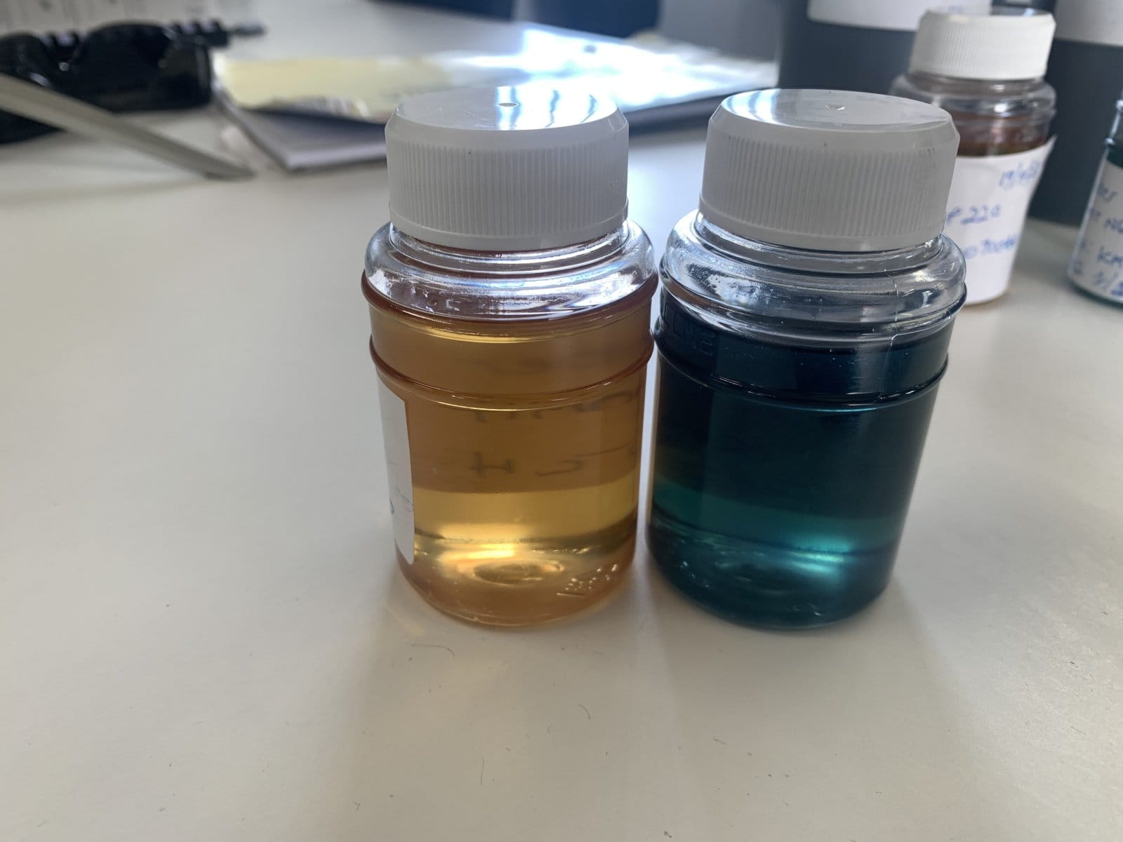
A larger oil reservoir isn’t always the answer to aeration, overheating or recurring contamination. The underlying issue may be too little effective rest time because oil moves quickly through a tank with a short-circuiting flow path. Problems that occur when there is too little reservoir/tank rest time or a high flow rate through a low-volume reservoir/tank can include air that has not escaped, particles that remain suspended and water that does not separate from the oil.
If you’re concerned that your reservoir can’t keep pace with system flow, start by examining how the tank works in operation. Capacity alone doesn’t show how long oil spends in the tank or whether baffles and line positions create a useful flow path. This article explains how reservoir volume, flow rate and effective residence time interact, and why a simple volume-to-flow calculation is only part of the picture. You’ll learn which warning signs warrant investigation, what checks can help distinguish a volume issue from poor flow distribution or operating conditions, and when oil-condition analysis or specialist fluid-cleanliness support may help inform the next step.
Key Takeaways
- Learn how usable reservoir volume and flow rate shape effective residence time, which can differ from the tank’s apparent capacity.
- Recognise potential effects of short reservoir rest time or high flow through a low-volume tank, including foaming, temperature changes or noisy operation.
- Use flow-path observations and operating records to help distinguish low usable volume from short-circuit flow and other possible causes.
- Review operating data, tank arrangement and oil-condition information before considering system changes.
- Understand how oil-condition analysis, filtration or flushing may support an investigation without replacing diagnosis of reservoir design and operating conditions.
Why short reservoir rest time can put lubrication performance at risk
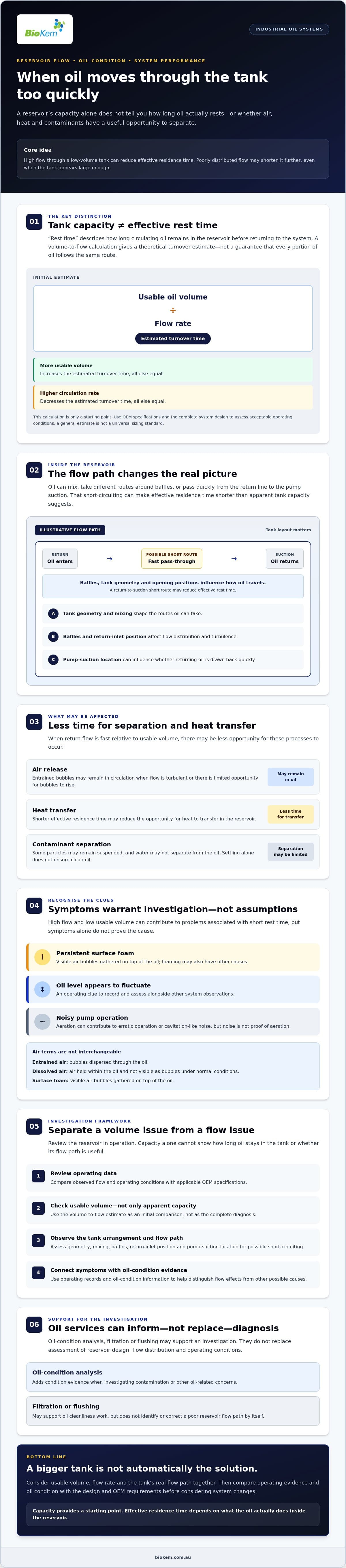
“Rest time” is a practical way to describe how long circulating oil remains in a reservoir before returning to the system. A simple estimate divides usable oil volume by flow rate. This gives a theoretical turnover time, not a guarantee that every portion of oil follows the same path or has the same opportunity for air release, heat transfer or separation.
Understanding the problems that occur when there is too little reservoir/tank rest time or a high flow rate through a low-volume reservoir/tank requires more than checking capacity. Tank geometry, mixing, baffles, return-inlet position and pump-suction location all influence effective residence time. Use the OEM specifications and the design of the complete system to determine acceptable operating conditions.
For context, this video examines aeration in a hydraulic motor and identifies insufficient tank size as a possible cause:
What does reservoir rest time mean in a circulating oil system?
A volume-to-flow calculation is useful for an initial comparison: increasing usable volume or reducing circulation rate increases the estimated turnover time. But a working tank isn’t a plug-flow vessel. Oil can mix, take different routes around baffles, or pass quickly from the return line to the suction if those openings are poorly positioned. This short-circuiting can reduce effective residence time even when total capacity appears substantial.
Theoretical turnover time is an estimate based on volume and flow; effective residence time reflects how long oil actually spends following the tank’s real flow paths. Check system expectations against applicable OEM documentation rather than treating a general rule as a universal sizing standard.
Why does a lubrication reservoir need more than storage capacity?
A reservoir stores oil, supports heat transfer and provides an opportunity for entrained air to escape. A controlled return path can reduce turbulence and give bubbles more opportunity to rise, while allowing some heavier contaminants to separate from the moving oil. These processes depend on operating conditions and tank design. Not every particle will settle, and settling alone does not ensure clean oil.
Reduced opportunity for separation may leave some contaminants circulating through lubricated components. Hydraulic fluid also transfers heat and supports contamination control, as outlined in this overview of hydraulic fluid functions. If contamination is a concern, oil-condition evidence matters. Microbial contamination in lube oil is one specific condition to distinguish from flow-related effects.
How high flow through a low-volume reservoir affects oil and equipment
When oil returns to a tank quickly relative to its usable volume, there may be less opportunity for entrained air to escape, heat to transfer and some contaminants to separate. Poorly distributed flow can intensify these effects by carrying return oil directly towards the pump suction. High flow and low usable volume can contribute to problems associated with insufficient reservoir rest time, but symptoms are clues, not proof of the cause.
Can inadequate residence time contribute to aeration or foaming?
Entrained air consists of bubbles dispersed through the oil. If the return flow is turbulent or the tank offers limited opportunity for bubbles to rise, some may remain in circulation. Dissolved air, by contrast, is held within the oil and isn’t visible as bubbles under normal conditions. Surface foam is made up of visible air bubbles gathered on top of the oil. These conditions are related, but they aren’t interchangeable, and foaming may have other causes.
Operators may notice persistent foam, a level that appears to fluctuate, or noisy pump operation. Aeration can contribute to erratic operation or cavitation-like noise, but suction-side air leaks, low oil level, oil condition and equipment design also warrant consideration. Symptoms alone cannot confirm inadequate reservoir rest time. Assess them alongside the oil’s condition, return-line arrangement and system design.
What can happen to heat and contaminant management?
A reservoir provides an opportunity for heat transfer, but oil temperature depends on the wider system, including its load and heat-transfer arrangement. High circulation and poor flow distribution may limit that opportunity, yet a warm tank alone doesn’t establish that capacity is inadequate. Similarly, reduced separation time may keep some heavier contaminants circulating rather than allowing them to settle. Settling won’t remove every particle or replace appropriate filtration and oil-condition monitoring.
Record where and when temperature changes occur, then compare them with operating conditions and a valid baseline. Note whether visible foam or an unstable level coincides with particular loads or operating states. These patterns can help narrow the investigation without assigning a cause based on a single observation.
Use the applicable OEM documentation, system design requirements and site procedures when assessing lubrication-system conditions. A general reference or rule of thumb can’t replace requirements specific to the asset and its operating environment.
If oil-condition concerns remain after operating conditions have been reviewed, BioKem’s oil-condition analysis or flushing services may support fluid-cleanliness work. These services don’t replace diagnosis of reservoir design and operating conditions. Review relevant oil-service requirements with the team.
How to tell a volume problem from poor flow distribution
Foaming, fluctuating oil levels or temperature changes can point to several different conditions. To investigate whether insufficient reservoir rest time or high flow through a low-volume tank is contributing, compare usable oil volume and actual circulation flow with the tank’s internal layout and operating records. No single symptom or calculation proves the cause.
| Possible cause | What to check | What the evidence may suggest |
|---|---|---|
| Low usable volume | Oil level during operation, working volume, and system drawings or specifications. | Available oil volume may be lower than the design requires, particularly under the conditions when symptoms appear. |
| High circulation rate | Measured or documented flow at relevant operating states; confirm pump and system configuration. | Flow may be high relative to usable volume, shortening the simplified turnover estimate. |
| Short-circuit flow | Return and suction positions, baffles, and the tank’s actual internal arrangement. | Oil may travel directly from return to suction, despite apparently adequate total capacity. |
| Other causes | Trend oil condition, level, temperature, pressure and operating events; check relevant equipment records. | Air ingress, oil condition, load changes or other system factors may better explain the symptoms. |
Which operating data help estimate effective reservoir turnover?
Record usable oil volume, not just the tank’s nominal capacity, and obtain the measured or documented circulation flow for the operating condition being investigated. Dividing volume by flow gives a simplified turnover estimate. It doesn’t show how oil moves through the tank or establish effective settling time. Compare the figures and observed behaviour with applicable equipment documentation and stated system design requirements. Don’t apply an unsupported universal threshold.
How can internal flow paths create short-circuiting?
If the return inlet and pump suction are close together, or baffles fail to guide flow, some returning oil may be drawn back into circulation before it has moved through much of the reservoir. Check drawings against the actual layout, including baffle positions and any changes made over time. If internal inspection is appropriate, it must follow site safety and isolation controls. Any proposed modification requires suitable engineering review.
Oil cleanliness provides additional context, but it doesn’t identify a reservoir fault by itself. Review sampling history and contamination trends alongside flow and design evidence. For broader context on one contamination pathway, see BioKem’s information on microbial contamination in lube oil. Consider the combined evidence to determine whether the concern relates to volume, flow distribution, operating conditions or a separate oil-condition issue.
What checks should maintenance teams perform before changing the system?
Before adjusting a reservoir or changing operating settings, build an evidence-based picture of how the system behaves. Investigating insufficient rest time or high flow through a low-volume tank starts with recording symptoms and checking actual conditions, rather than assuming tank capacity is the cause.
What should operators record during the investigation?
Use a consistent sequence so observations can be compared across operating conditions:
- Record symptoms: note when foaming, turbulence, unstable level, unusual temperature or noisy operation occurs, and what the equipment is doing at the time.
- Confirm operating data: document circulation flow if available, operating state, oil level, temperature and pressure. Compare with manufacturer documentation and site procedures.
- Review the flow arrangement: check the tank drawing against the return and suction locations, baffles and actual internal layout where safely accessible.
- Check oil-condition evidence: review available analysis results, sampling history and previous condition records for relevant changes or recurring cleanliness concerns.
Trend temperature, level and pressure against a valid baseline, alongside oil-condition information where available. Record visible foam or turbulence consistently rather than relying on descriptions such as “worse than usual.” A change that coincides with a particular load or operating state can help focus the investigation, but it doesn’t prove a single cause.
When should the issue be escalated for engineering review?
Seek engineering review if aeration persists, temperatures are abnormal, cleanliness concerns recur or equipment behaviour remains unstable. The assessment should consider usable oil volume, actual flow, tank layout and suction conditions together. Oil sampling or other appropriate condition monitoring can provide supporting evidence. Compare results with system requirements and historical records before drawing conclusions.
Don’t reduce flow, alter a tank or change setpoints on critical equipment without the required technical review and site controls. Such changes can affect lubrication delivery and equipment operation. Filtration may be relevant if the investigation identifies an oil-cleanliness issue, but it won’t correct poor reservoir design or unsuitable operating conditions. BioKem provides filtration support for fluid-cleanliness needs where findings indicate it may be relevant.
For oil-service support informed by your investigation, share your findings with BioKem.
How specialist oil services can support reservoir and flow investigations
Once operating conditions and tank arrangement have been investigated, specialist oil services may help address a related fluid-cleanliness issue. Oil-condition analysis can provide evidence about the oil, while filtration or flushing may be relevant when contamination is identified or cleanliness requirements call for it. These services can support the wider investigation, but they don’t redesign a reservoir or correct unsuitable flow paths.
When might filtration or flushing support be relevant?
When investigating insufficient reservoir rest time or high flow through a low-volume tank, first establish whether oil cleanliness is part of the issue. BioKem offers onsite and lab-based patch analysis, which can help assess particulate contamination. Consider findings alongside operating data, system requirements and other available oil-condition information.
If the investigation identifies a need to remove contamination from the system, flushing may be considered as part of a defined scope. BioKem has kidney-loop and high-flow flushing capability. High-flow flushing is not a remedy for insufficient reservoir volume, ineffective baffling or return-to-suction short-circuiting. Those design and operating conditions still require appropriate technical review. If flushing is indicated, see the guide to hot oil flushing and filtering.
What information helps begin a technical discussion?
Useful information connects oil-condition findings with the system’s design and operation. Prepare what’s available, such as:
- System drawings and details of the tank’s internal arrangement.
- Usable tank volume and measured or documented flow information.
- Operating conditions, including when symptoms occur and any relevant temperature, level or pressure records.
- Oil-condition results, patch analysis or other cleanliness evidence.
BioKem supports energy, gas, mining, manufacturing and heavy-industry sectors across Australia. Sharing observed symptoms and available records can help frame a practical discussion about whether oil-condition analysis, filtration or flushing is relevant. These services support fluid cleanliness; they don’t replace engineering diagnosis of reservoir design or operating conditions.
Discuss your lubrication system with BioKem, including the symptoms you’ve observed and the operating data available.
Make your next system decision with confidence
Reservoir capacity is only part of the picture. Actual flow, usable oil volume and internal tank arrangement together shape effective residence time, while foaming, temperature changes or unstable operation are clues to investigate, not proof of a tank-volume problem. Assess whether insufficient rest time or high flow through a low-volume tank is contributing by comparing operating evidence with the system design before changing critical equipment.
Where oil cleanliness is also a concern, BioKem offers onsite and lab-based patch analysis, plus kidney-loop and high-flow flushing capability. These services can support fluid-condition work, but they don’t replace assessment of reservoir design or operating conditions. BioKem’s staff bring over 70 years of combined industry experience.
Bring together your system drawings, available flow and operating data, symptom records and oil-condition results. Then discuss your lubrication system with BioKem to explore relevant oil-service support. An evidence-led investigation can help identify an appropriate next step for reliable equipment operation.
Frequently Asked Questions
What happens if a hydraulic reservoir is too small?
A hydraulic reservoir that is too small for its duty may provide less opportunity for oil to release entrained air, transfer heat and allow some contaminants to separate. The impact depends on usable volume, circulation rate, tank geometry, baffling, oil condition and operating state. A small tank alone doesn’t establish the cause of a fault. Compare symptoms and system data with design documentation and applicable engineering requirements before proposing a change.
How do you calculate reservoir residence time?
Divide usable oil volume by the flow rate through the reservoir, using compatible units. The result is a simplified estimate of theoretical turnover time, not a measure of how long every portion of oil spends in a settling zone. Mixing, baffles, inlet and outlet positions, and changing operating conditions affect actual flow. Use the calculation as an initial screening tool, not as a universal design rule or proof of effective residence time.
Can high flow through a low-volume tank cause oil aeration?
Yes, it can limit the opportunity for entrained air to separate, especially if return flow creates turbulence or travels directly towards the pump suction. Aeration may also result from air leaks, return-line configuration or operating conditions. Foam or bubbles alone don’t identify the cause. Review the tank arrangement, flow conditions and equipment data before attributing aeration to reservoir volume, and have persistent or concerning symptoms investigated appropriately.
What are the signs of poor oil reservoir circulation or insufficient rest time?
Possible signs include persistent aeration or foaming, visible turbulence, unusual temperature behaviour and recurring cleanliness concerns. These clues can have multiple causes, so they aren’t diagnostic on their own. Assess potential effects of insufficient reservoir rest time or high flow through a low-volume tank alongside operating evidence. Record when symptoms occur and compare them with normal operating conditions, system data and reservoir design.
Does a larger reservoir always solve short oil rest time?
No. More usable volume may increase theoretical turnover time, but it won’t necessarily correct short-circuit flow, ineffective baffling, poor inlet placement or another system issue. A capacity change must also suit the equipment design and operating requirements. Before modifying a reservoir, determine whether volume, circulation rate, flow distribution or another condition is contributing to the symptoms. Review any proposed change against applicable system documentation and engineering requirements.
How can you reduce turbulence in an oil reservoir?
Start by reviewing return-line and suction locations, baffles, operating flow and tank design against available system documentation. The appropriate response depends on the equipment and may require engineering assessment. Don’t make unverified changes to a critical lubrication system, including altering internal arrangements or reducing flow. Confirm that any proposed adjustment suits the application and maintains the equipment’s specified operating requirements before implementation.
Should oil be sampled when reservoir rest time may be inadequate?
Oil sampling can provide evidence about oil condition or cleanliness, but it doesn’t measure residence time or prove that reservoir volume is the cause. Use an appropriate sampling method and interpret results alongside operating records and system inspection. BioKem offers onsite and lab-based patch analysis, which may support a wider investigation when relevant. Combine condition evidence with flow and tank-design information to help identify an appropriate next step.

Article by
James McAllister
James McAllister is an industry professional with BioKem Oil Services, specialising in lubrication reliability, oil filtration, contamination control and asset performance. Drawing on BioKem's extensive field experience across turbines, compressors, hydraulic systems and critical rotating equipment, James writes practical, insight-driven articles that help maintenance and reliability teams improve equipment performance, extend asset life and reduce operational risk.
Disclaimer
The information contained in this article is provided by BioKem Oil Services for general informational and educational purposes only. While every effort has been made to ensure the accuracy and relevance of the information at the time of publication, BioKem Oil Services makes no representations or warranties, express or implied, regarding its completeness, accuracy, reliability, suitability or availability.
Readers should seek professional advice before making maintenance, operational, engineering or investment decisions based on the content of this article. BioKem Oil Services accepts no liability for any loss, damage or consequential loss arising from the use of, or reliance upon, the information presented.
Unless otherwise stated, all content, including text, graphics, images and technical information, is the property of BioKem Oil Services and is protected by applicable copyright and intellectual property laws. No part of this publication may be reproduced, copied, distributed, republished, stored, transmitted, modified or used in any form without the prior written permission of BioKem Oil Services.
© BioKem Oil Services. All rights reserved.